
Lasergate is a PoE-powered light-barrier device built on the ESP32-S3, meant to watch doorways or other openings and report when something passes through. Instead of a camera, it uses pairs of modulated lasers and LDRs. No image data, no object detection model, no privacy questions to answer.
This is a hobby project I'm building in my spare time, not a finished product. Firmware, mechanics and electronics are all still in flux.
Work in progress. What exists right now:
Firmware
- ESP-IDF/FreeRTOS firmware for the ESP32-S3, split into a hardware abstraction layer (GPIO, ADC, NVS, Ethernet, HTTP server, MQTT, time, random) and the application logic on top of it
- A state machine covering the whole device lifecycle: initializing, beam adjustment, LDR threshold calibration, pulse frequency calibration, observing, self-test, GPIO discovery, disarmed, alarm, fault and shutdown
- Modules: laser pulsing with a pseudo-random pattern, pattern verification on the LDR side, and a gate class that ties up to four modules together and raises the alarm
- Modules calibrate themselves against ambient light rather than needing manual tuning. Both routines (LDR threshold, pulse frequency) persist their results to NVS, so a module doesn't have to recalibrate after every reboot
- A signal/noise self-test that reports how many pulse batches each module misread
- GPIO discovery mode for freshly assembled hardware, with raw ADC readings and manual pin toggling
- Pin validation against the board's reserved pins, and each LDR is routed to the ADC unit its pin belongs to
- Settings reset to defaults, and per-module and device configuration stored in NVS
Web UI
- A single-page web UI served straight from the device, with pages for the dashboard, emitters, LDR calibration, frequency calibration, modules, self-test, GPIO discovery and configuration
- Live state pushed over a websocket, plus a header bar with state, uptime and module count, and a fault banner
- Each task page is live only in its own state. In any other state it links to the running task or offers an enter button when the transition is allowed
- Narrow screen layout for phones
- A stdlib-only preview server (
tools/webui-dev-server.py) fakes the firmware API, so the UI can be worked on without a device
Tests
- 31 Catch2 test suites running on a dev machine with no hardware attached, against stubs for GPIO, ADC, NVS, time, MQTT, Ethernet and the HTTP server
- Coverage spans the low-level wrappers, module/gate/calibration logic, the state machine, settings, the API controller and JSON output. An LDR physics simulation feeds the calibration tests
Hardware
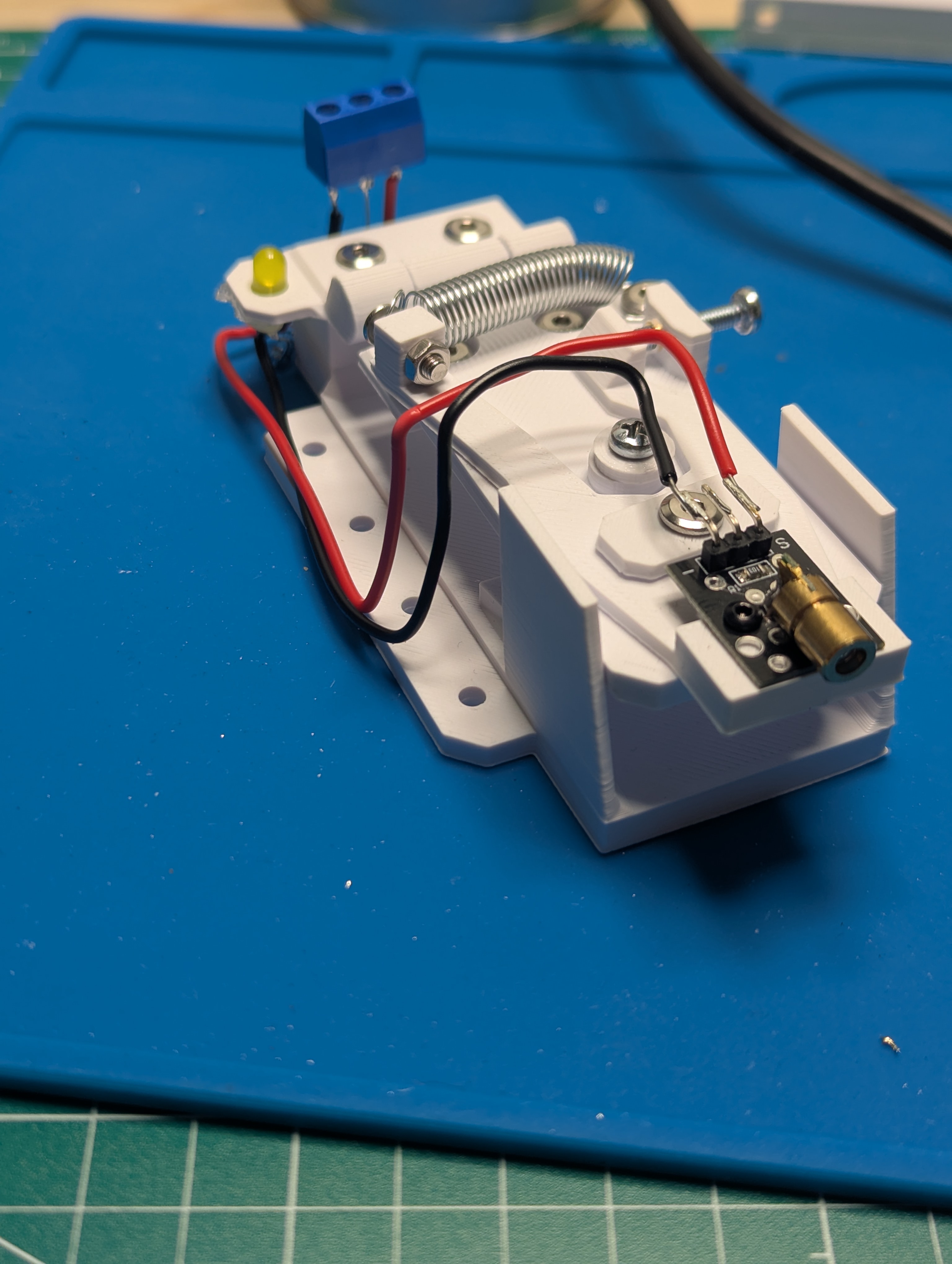
- Mechanical prototypes for the sensor modules
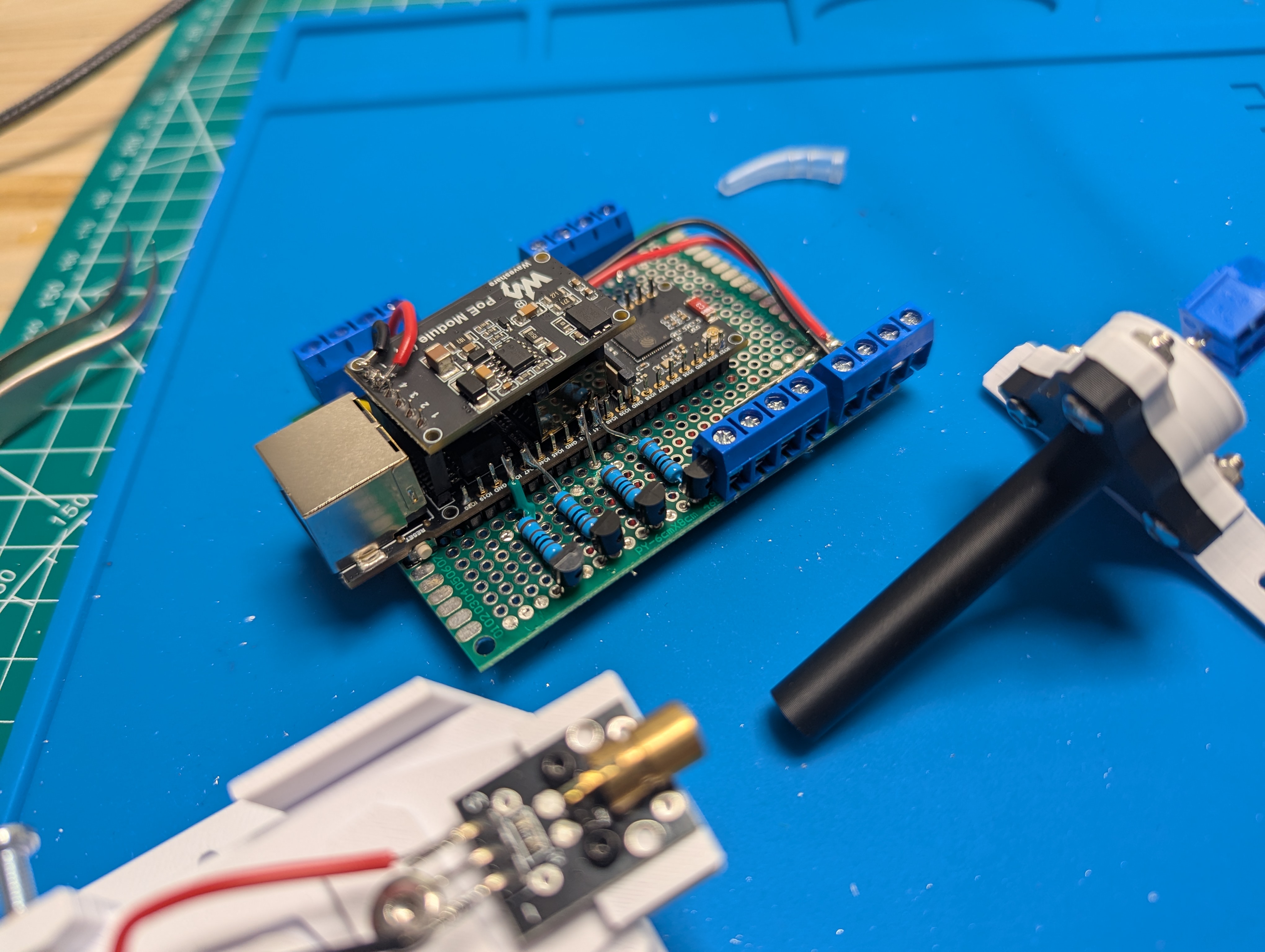
- A first electronics prototype: ESP32-S3 with a PoE HAT, breadboarded laser/LDR module
Not done yet
- Alarm outputs: MQTT connects and publishes availability, but alarm events aren't published yet. No webhook.
- The alarm trigger condition is a set of compile-time tunables, not yet exposed in the web UI
- Final electronics, enclosure and mounting
Each sensor is a laser/LDR pair, called a module. A gate is made up of however many modules you need to cover an opening. The main limit is the number of available GPIO (and ADC-capable) pins on the development board. Currently capped to four modules.
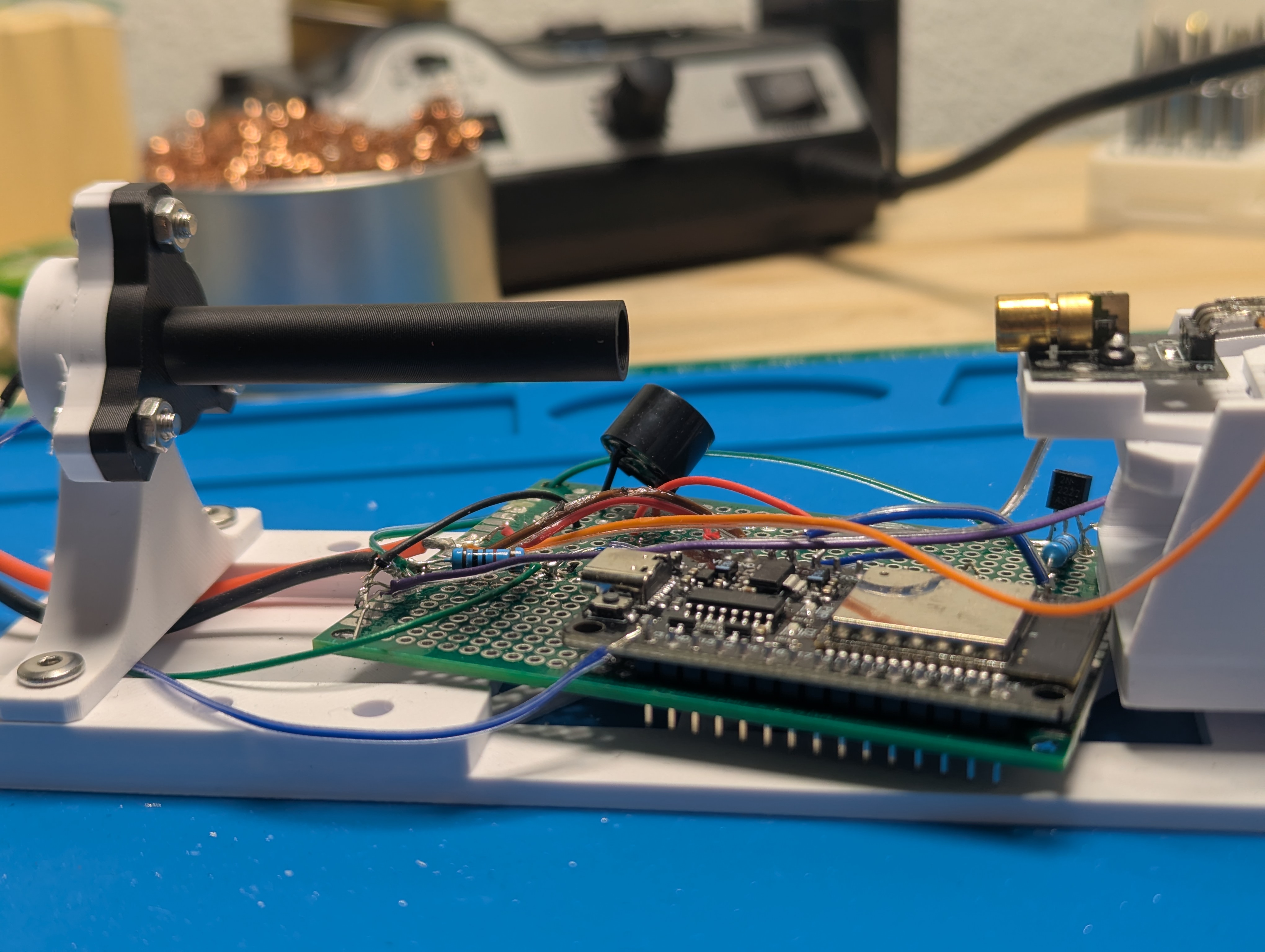
The laser is pulsed with a pseudo-random pattern instead of just being on or off, and the receiving LDR checks the incoming signal against the expected pattern rather than reading a plain brightness threshold. That should make the thing harder to fool with a flashlight or a well-timed hand wave than a basic light barrier would be. A long, narrow black tube in front of each LDR blocks stray light from the sides so the sensor mostly only sees its own laser. The alarm trigger condition (how many modules need to be blocked at once, and for how long) is meant to be configurable.
Working: a web UI and JSON API served over HTTP on the Ethernet connection, with live state pushed over a websocket. The UI covers status, calibration, self-test, GPIO discovery and settings. MQTT support is implemented and connects to a configured broker, but the application only publishes its availability so far.
Planned: an HTTP webhook for alarms and alarm events over MQTT.
| Fifth-iteration laser/LDR module prototype | Glare-shield tube prototype, ESP32 nodemcu (not yet S3) | First PoE board, ESP32-S3 with W5500 |
|---|---|---|
 |
 |
 |